To Create a Single Floor Plan, by User Definition method
-
Select
 (Create Floor
Plan). In the tool setting window, select
(Create Floor
Plan). In the tool setting window, select
 (Plan By User Definition).
-
Set the
Drawing Seed that you want to use.
Click on the field and select a seed from the pull down list.
-
Set the
Plan Cut Elevation.
The Plan Cut Elevation is the actual Z Elevation where the section plane cuts through the model.
- Set the View Ranges. Set the values for Back, Cut and Forward distance. The Back Offset is the distance above the Cut, and the Forward Offset is the distance below the Cut.
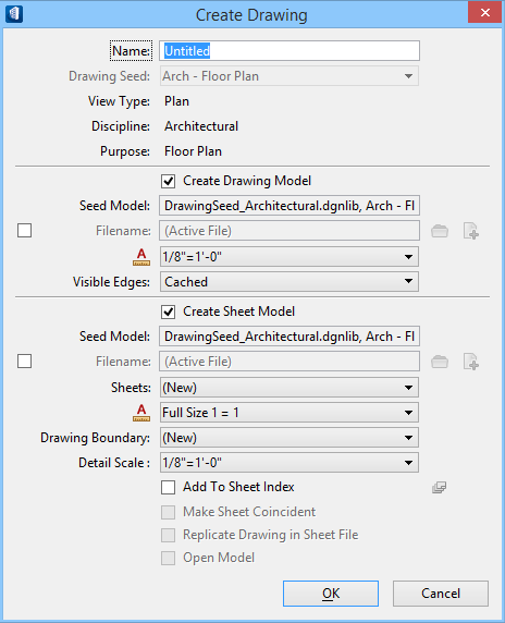
- (Optional) Turn on Create Drawing if you want to create a drawing.
-
Issue a Data Point in the view to place the dynamic floor plan
section clip. Issue a second Data Point to accept.
The floor plan view is created and the section clip volume cutting plane is now visible in the view.
- (Optional) If you turned on Create Drawing, the Create Drawing dialog opens when the dynamic floor plan is created. If you want to create a Drawing Model and/or Sheet Model, turn on the appropriate check boxes and click OK. Turn on the Filename check boxes if you want to create unique names for the models.
- (Optional)
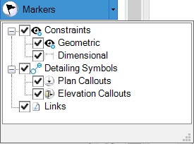
In the View Attributes dialog, Presentation Panel, expand the
Markers setting and turn on Detailing Symbols and Plan Callouts.
This enables the display of symbol and callout markers in the model. Use the markers to select symbols and callouts. The markers also invoke the Mini Toolbar which contains tools to manage symbols and callouts.
- Reset to complete dynamic floor plan creation.